IAR-80FA project creates a replica of the historical Romanian WW2 Fighter IAR-80. From airworthiness point of view, a historical a/c replica is classified as non-EASA, in other words, no EASA certification needed to fly, but a flight permit released by national authority.
However, to obtain the flight permit we need to convince the national authority that the aircraft is airworthy. Nobody can tell as beforehand what is the minimum documentation shown to the authorities, as there are no Romanian rules for non-EASA requirements. In these conditions we have chosen EASA rules, from CS-23, and proceed to release documents like for certification of a new aircraft.
It is likely that we can produce more than necessary for a flight permit. But do not forget one of the reasons our organization was created. IAR-80FA documentation will be entirely public to show new generations what any other commercial organizations keep inside.
Like any other new aircraft, IAR-80FA must follow all the necessary steps for the certification. This is because there is limited original documentation and there are no certification documents. IAR-80FA must comply with all CS 23 requirements.
Previously, it was announced that the Stress Manual Fly Again is ready. This is a compilation of more than 100 spreadsheets in Excel and free Mathcad Express, divided into 26 chapters, which will allow the engineers to proceed with the specific strength calculation necessary for the certification of the IAR-80FA. Notice that only public resources were used. The manual was created by Mr. Ion Adam (Senior Stress Engineer) who is guiding us through the journey of IAR-80FA Checkstress. Thus, the Stress team is ready to take the next steps in the creation of the Checkstress reports that will demonstrate the integrity and strength of the structure.
Within the following, we will share with you the analysis performed for the Horizontal Stabilizer’s Front Spar, Rear Spar and stringers using Engineering Beam Theory [EBT].
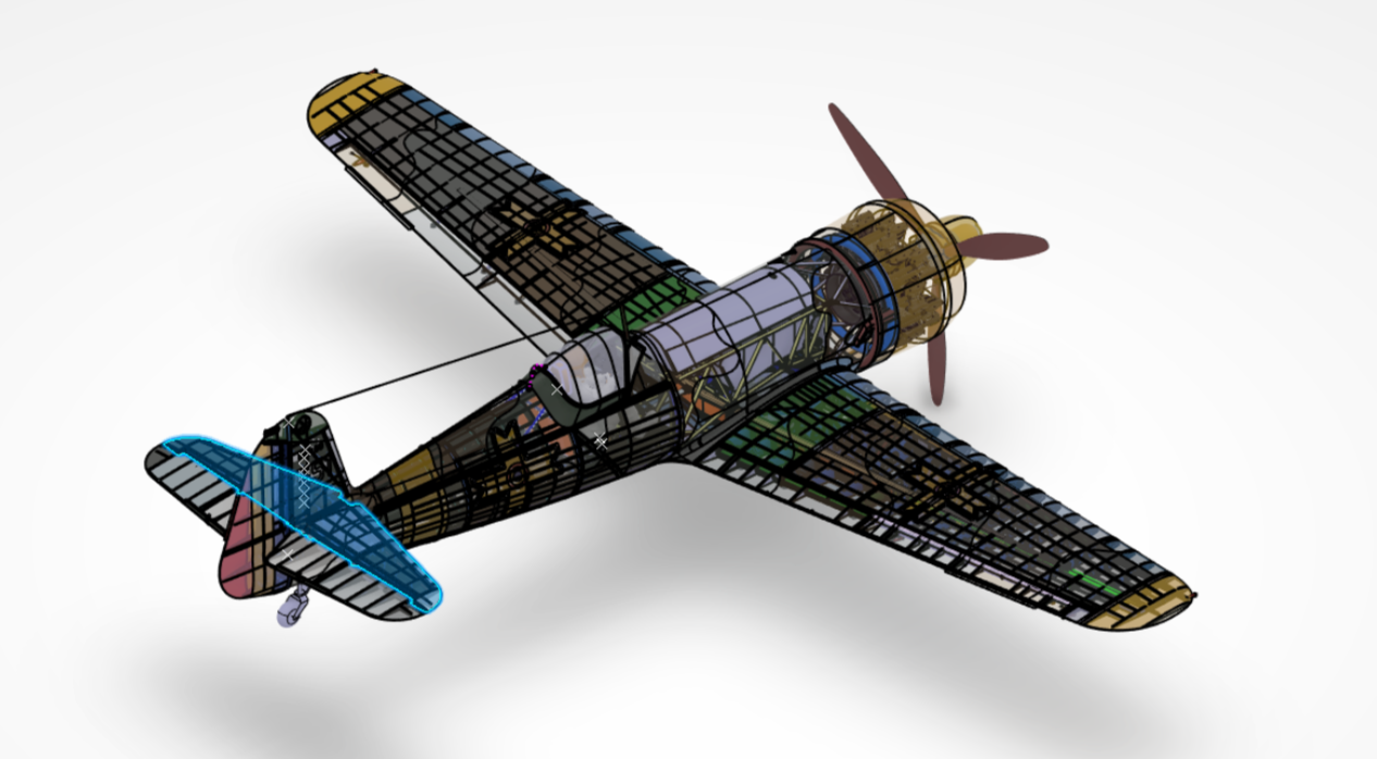
Engineering Beam Theory (or Euler-Bernoulli Beam Theory) is a simplification of the Linear Theory of Elasticity, through which it can be determined the load-carrying and deflection capabilities of a beam. The simplicity of this theory makes it a very important tool in mechanical engineering, as it allows us to describe forces, moments, stresses, and deflections for beams under bending. For aerostructures, the Engineering Beam Theory is developed by considering the instability of thin shells under compression and shear, with load redistribution due to semi diagonal tension field. Thus, ETB becomes nonlinear.
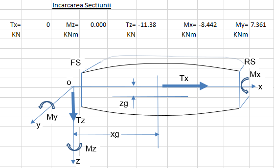
The analysis performed for the Stabilizer Longitudinal Structure is done within one of the Excel spreadsheets created for the Engineering Beam Theory. We won’t dive into every detail of the analysis, but we would like to share with you some information related to the main input data needed to perform such a calculation.
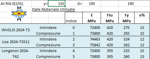
From the beginning, it is deemed necessary to define the material properties of the parts subjected to the analysis. It must be mentioned that the materials chosen for the entire airframe structure are the modern equivalent of the original materials that IAR used 80 years ago. These materials are analyzed and described following CS-23 regulations within a dedicated technical report.
The Horizontal Stabilizer Skins are made of Al 2024-T3 clad, the stringers are made of Al 2024-T3511 extrusion, and the spars are made of Al 2024-T42 clad. Within the analysis the B basis is chosen for skins and stringers and A basis for spars.
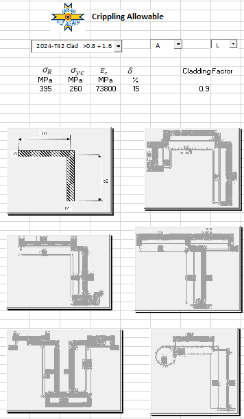
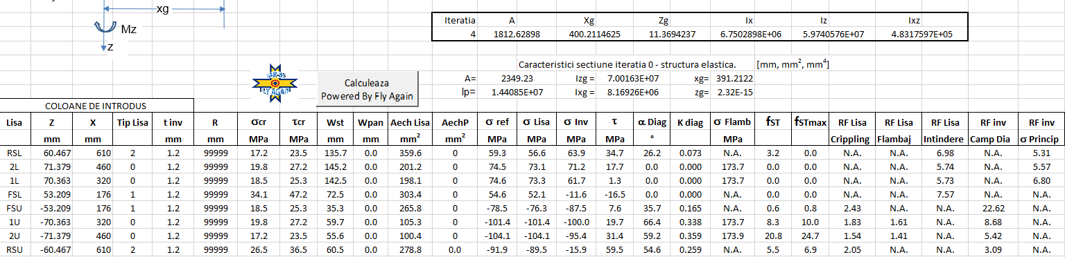
Further for the analysis, it is required to determine the mechanical properties of the spars and stringers. Besides areas, moments of inertia, or centers of gravity, it is required to determine the crippling allowable for each configuration.
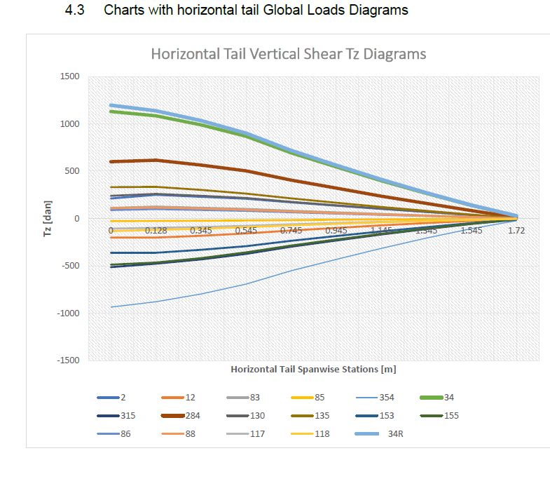
For the selection of the load cases, the Global Loads Diagrams for the IAR-80FA technical report was brought into play. Used in Strength of Materials for beams, the loads diagrams for shear, bending, and torsion allow simple stress calculations for critical loading cases and critical sections. Having the load diagrams makes it easier to decide which loading cases are critical. From this report, it follows that two load cases are covering the entire empennage span: 34R and 354.
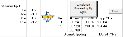
There is only one step left: the one where the calculation point is defined together with the type of longitudinal structure and skin thickness. With this data added to the spreadsheet, a quick press of the “Powered by Fly Again” button will lead to the results (reserve factors for crippling, buckling, and tension for stringers, semi-diagonal tension, and sigma1 principal for skin).
Using the same ETB sections idealizations, the Stress Manual also offers a procedure to evaluate the ETB factors, which are the stress ratios, of any element, for any specified load case, between the nonlinear and linear calculations. These ETB factors can be applied to linear FEA results, for more detailed evaluation.
Needless to say, the Stress Manual of IAR-80FA becomes a powerful tool to determine the strength of the parts by hand calculation, allowing the stress engineers to enjoy this type of activity and to increase their know-how.
Hoping that you enjoyed the story so far, we would like to ask you to stay tuned for our next episode: the creation of the certification report for the Horizontal Stabilizer longitudinal structure. A new adventure with lots of satisfaction for us!
To be continued,
Alexandra and Ilinca Camarasu